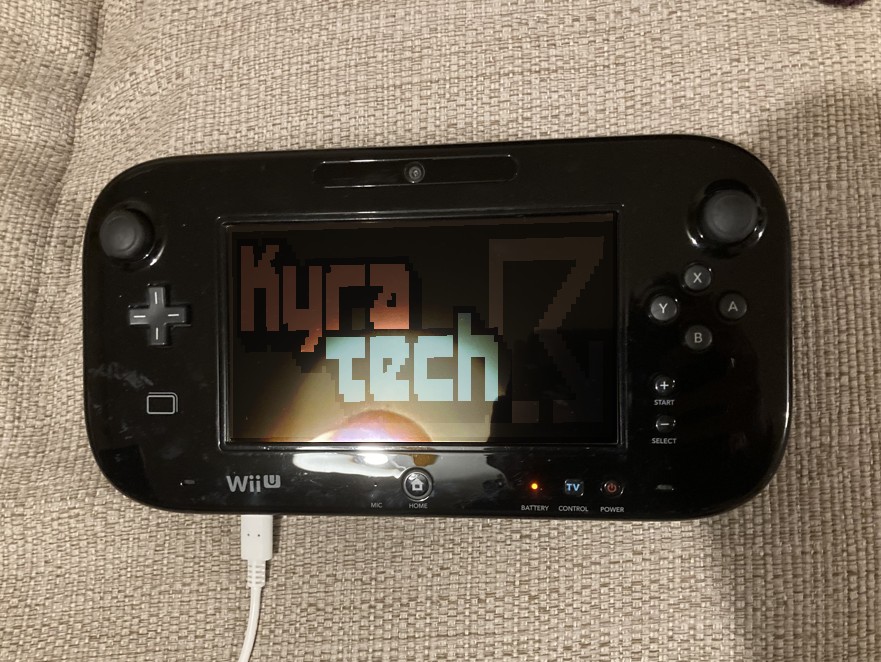
USB-C WiiU Gamepad
My parents were given a used WiiU to serve as a HDMI-compatible Wii, but unfortunately the charging port on the gamepad was broken (and the charging cable itself was AWOL). Fuelled by unfounded confidence and a stubborn refusal to create e-waste, I decided to bring the gamepad home and see if I could fix it using the contents of my electronics bin.
USB-C gamepads are a solved problem
A quick google informed me that USB-C mods on WiiU gamepads have already been achieved a few times, so I knew that this project was viable: In-place USB-C breakout pcb, Soldering a USB-C female connector directly to the gamepad mobo, USB-C Mod ribbon pcb mod on Tindie. However, I didn’t have the parts lying around to replicate any existing mod 1:1, so I would need to improvise a little.
By the way, I am a dumbass inexperienced when it comes to electronics, so perhaps refer to this page with a pinch of salt.
I had two options for USB-C ports available to me, both being breakouts intended for maker projects. The sparkfun breakout board was larger but included the two CC resistors that tell an upstream port to provide 5V 1.5A. The official WiiU Gamepad charger supplies 4.75V 1.6A, which is probably Close Enough (tm).
The unbranded breakout was compact, but the lack of resistors meant that you could probably blow up the gamepad if you used a USB-C to USB-C cable to charge it. Again, because I am inexperienced, I decided to err on the side of caution and go with the other one.
How does the original charging port work?
Because I wasn’t following an existing guide to the letter, I needed to do some investigating to work out which pins on my breakout board I needed to connect where. A visual inspection of the charging port indicated that there were two contacts inside the female housing.
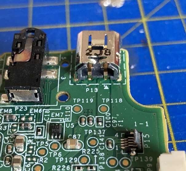
I used the continuity setting on my multimeter to check which parts were connected. Turns out that the metal housing was connected to one of the contacts, which was in turn connected to the ground of the motherboard. Given that at least one of the contacts had to be power, I knew then that the port only used VCC and Ground.
Is that surprising to people who know what they are doing? I was surprised.
Based either on wild guessing or something that I saw in one of the other USB-C mods, I also tested the two nearby pads on the motherboard and found that they exposed direct connections to the contacts in the charging port. Neat.
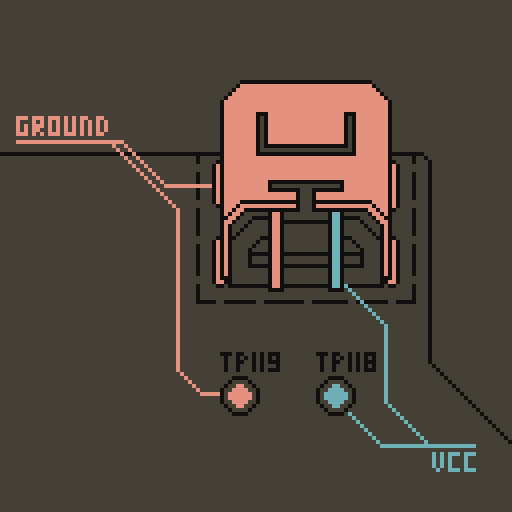
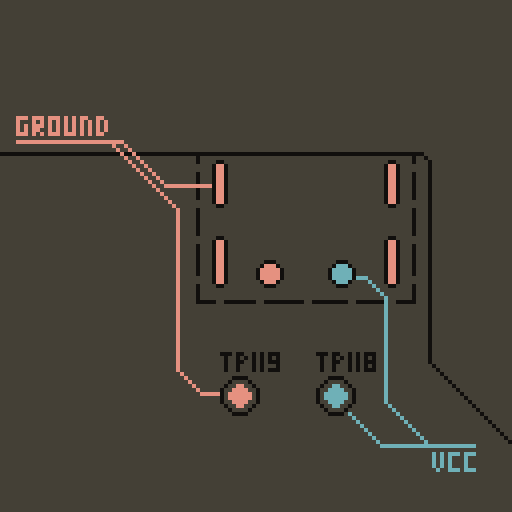
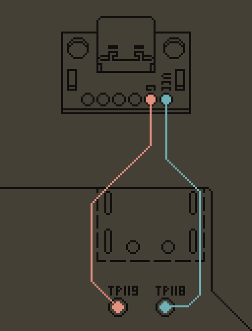
I decided to connect my USB-C breakout to the pads TP119 and TP118. Because of this, it was unnecessary to remove the original charging port, but I decided to do it here because said port was - at least - superficially broken.
I tried my best to desolder it using my soldering iron and a solder sucker, but it wasn’t taking, and my attempts to liquidise all the mounts at once didn’t work. My successful method for port removal involved judicious use of wire cutters followed by desoldering the shrapnel left over, one mount at a time.
Connecting the new power port
Using a scribbled version of the diagram above, I soldered some wires to the pads on the motherboard and those wires to my breakout board. This turned out to be a particularly tricky soldering job; I don’t know if the manufacturer treated the PCB with anything, but the pads did not want to be tinned even after using Probably Too Much flux. It was like hydrophobic fabric, but for solder. As a result, you are about to see some SHOCKING solder joints and I can only ask that you forgive my crimes against electronics. I fully expect to be repairing this job near in the future.
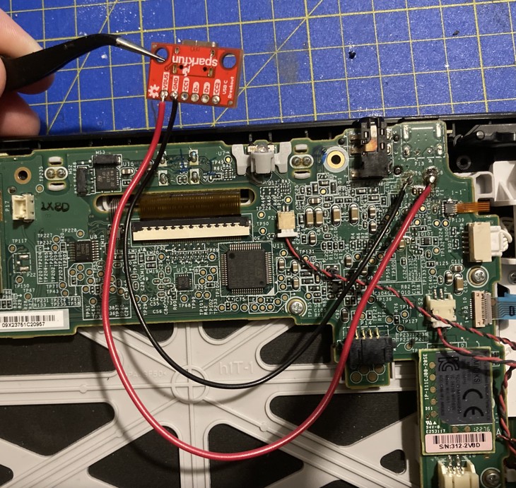
I apparently don’t have multi-core wire in my electronics box, which I need to rectify post-haste. This would work so much better with a more flexible wire. (I do have ultra-thin wires for repairing PCB traces, but I didn’t want to risk putting 1.5A through them.)
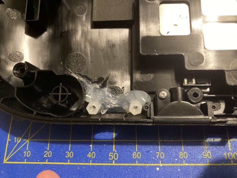
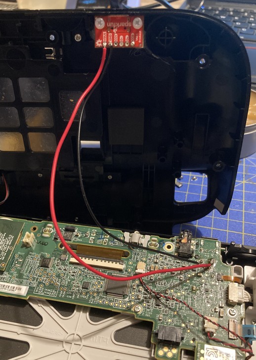
Unfortunately, the USB-C breakout board that I was using was too big to fit where the original power port was located. Luckily, there was an appropriately sized void at the bottom of the gamepad that was big enough.
I drilled a hole in this area, then sanded it slightly too much using my rotary tool. Oops.
I didn’t want to permanently affix the breakout PCB to this part of the case because it is a different part of the shell from where the motherboard is mounted, and it would mean that I would have to desolder the wires whenever I wanted to open it up again. So, instead of gluing it in place, I screwed some spacers to the breakout and then glued those in place. Now I only need to undo two screws to separate the halves of the gamepad.
In conclusion
I feel like I’ve committed video game history vandalism. However! Something that was not usable before is now usable. That makes me feel accomplished, even though my repairs are far from neat.
My homework:
- Get multi-core wire
- Get a hot plate or hot air gun to make desoldering less miserable
- Practice surface mount soldering
